Prueba de detección de
conexión física
Fecha: 22 de Agosto del 2012
Objetivo: verificar si teniendo la interface en DOWN se puede
detectar o no el medio físico conectado en una interface WAN.
Hay técnicos que tienen la teoría que desde el router
NO se pueden verificar las conexiones físicas (Layer 1 o capa 1 OSI),
con este laboratorio se intenta demostrar de que si
la interfaz está en buenas condiciones eléctricas, puede verse el medio
conectado aunque esté DOWN-DOWN.
El medio físico detectado es el cable serial, tanto
V.24 como V.35 y tanto DTE como DCE, no la extensión pin-to-pin que
llega hasta el ATM.
Si la interfaz tuviese algún problema eléctrico
(quemada pr una tormenta), no podrían verse dichas conexiones (aunque esto
no lo puedo demostrar sin quemar adrede una placa
WIC-2T ...pero lo dejamos para la próxima ).
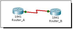
Prueba de detección de conexión física con un
simulador:
Con las interfaces en UP:
Router_A#sh int s0/0/0
Serial0/0/0 is up,
line protocol is up (connected)(Layer 2)
Hardware is HD64570
Internet address is 10.0.0.1/30
MTU 1500 bytes, BW 1544 Kbit, DLY 20000 usec,
reliability 255/255, txload 1/255, rxload 1/255
Encapsulation HDLC, loopback not set, keepalive set (10 sec)
Last input never, output never, output hang never
---resumido---
0 carrier transitions
DCD=up DSR=up DTR=up
RTS=up CTS=up
Router_A#sh controllers
s0/0/0
Interface Serial0/0/0
Hardware is PowerQUICC
MPC860
DTE V.35 TX
and RX clocks detected (Cable detectado, en este
caso DTE)
idb at 0x81081AC4, driver
data structure at 0x81084AC0
SCC Registers:
General
[GSMR]=0x2:0x00000000, Protocol-specific [PSMR]=0x8
Events [SCCE]=0x0000, Mask
[SCCM]=0x0000, Status [SCCS]=0x00
Transmit on Demand
[TODR]=0x0, Data Sync [DSR]=0x7E7E
---resumido---
Con las interfaces en DOWN:
Al ser punto a punto, se colocó en DOWN la interfaz
del Router_B, bajando obviamente la interfaz en Router_A

Router_A#
%LINK-5-CHANGED: Interface
Serial0/0/0, changed state to down
%LINEPROTO-5-UPDOWN: Line
protocol on Interface Serial0/0/0, changed state to down
Router_A#sh int s0/0/0
Serial0/0/0 is down,
line protocol is down (disabled)(Layer 2)
Hardware is HD64570
Internet address is 10.0.0.1/30
MTU 1500 bytes, BW 1544 Kbit, DLY 20000 usec,
reliability 255/255, txload 1/255, rxload 1/255
Encapsulation HDLC, loopback not set, keepalive set (10 sec)
---resumido---
0 carrier transitions
DCD=down DSR=down DTR=down
RTS=down CTS=down
Router_A#
Router_A#sh controllers
s0/0/0
Interface Serial0/0/0
Hardware is PowerQUICC
MPC860
DTE V.35 TX
and RX clocks detected (Cable detectado)
idb at 0x81081AC4, driver
data structure at 0x81084AC0
SCC Registers:
General
[GSMR]=0x2:0x00000000, Protocol-specific [PSMR]=0x8
Events [SCCE]=0x0000, Mask
[SCCM]=0x0000, Status [SCCS]=0x00
Transmit on Demand
[TODR]=0x0, Data Sync [DSR]=0x7E7E
Interrupt Registers:
---resumido---
Se colocó en UP la interfaz del Router_B y en DOWN
la interfaz del Router_A, bajando obviamente la interfaz en Router_B
para verificar si también se reproduce en cables
tipo DCE:
Router_B#sh int s0/0/0
Serial0/0/0 is down,
line protocol is down (disabled)(Layer 2)
Hardware is HD64570
Internet address is 10.0.0.2/30
MTU 1500 bytes, BW 1544 Kbit, DLY 20000 usec,
reliability 255/255, txload 1/255, rxload 1/255
Encapsulation HDLC, loopback not set, keepalive set (10 sec)
---resumido---
0 carrier transitions
DCD=down DSR=down DTR=down
RTS=down CTS=down
Router_B#sh controllers
s0/0/0
Interface Serial0/0/0
Hardware is PowerQUICC
MPC860
DCE V.35,
clock rate 128000 (Cable detectado, en este caso
DCE como los que conectan a los ATM)
idb at 0x81081AC4, driver
data structure at 0x81084AC0
SCC Registers:
General
[GSMR]=0x2:0x00000000, Protocol-specific [PSMR]=0x8
Events [SCCE]=0x0000, Mask
[SCCM]=0x0000, Status [SCCS]=0x00
Transmit on Demand
[TODR]=0x0, Data Sync [DSR]=0x7E7E
Interrupt Registers:
Config [CICR]=0x00367F80,
Pen
---resumido---
En caso de una hipotética interfaz quemada:
Router_A#sh controllers
s0/0/0
Interface Serial0/0/0
Hardware is PowerQUICC
MPC860
No serial cable attached
idb at 0x81081AC4, driver
data structure at 0x81084AC0
SCC Registers:
General [GSMR]=0x2:0x00000000,
Protocol-specific [PSMR]=0x8
---resumido---
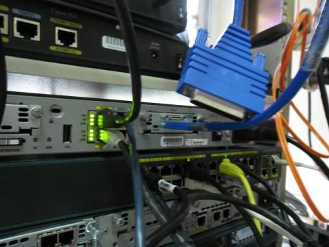
Prueba de detección de conexión física con equipo
real:
Para verificar que sin tener ningún medio conectado
mas allá del cable WAN, puede detectarse igualmente el tipo de medio,
en este caso un cable V.24 DCE similar a las
conexiones a los ATM.
1841_WAN#
1841_WAN#conf t
Enter configuration
commands, one per line. End with
CNTL/Z.
1841_WAN(config)#int
s0/0/0
1841_WAN(config-if)#shut
(bajamos la interfaz para descartar dudas del estado
de la interfaz)
1841_WAN(config-if)#
*Aug 22 17:58:52.295:
%LINK-5-CHANGED: Interface Serial0/0/0, changed state to administratively down
1841_WAN(config-if)#
1841_WAN(config-if)#no
shut (subimos la interfaz para descartar dudas del
estado de la interfaz)
1841_WAN(config-if)#
*Aug 22 17:59:00.323:
%LINK-3-UPDOWN: Interface Serial0/0/0, changed state to down
1841_WAN(config-if)#
1841_WAN(config-if)#end
1841_WAN#
1841_WAN#sh int s0/0/0
Serial0/0/0 is down,
line protocol is down (Layer 2)
Hardware is GT96K Serial
Internet address is 172.16.0.1/30
MTU 1500 bytes, BW 128 Kbit, DLY 20000 usec,
---resumido---
0 carrier transitions
DCD=up DSR=up DTR=down
RTS=down CTS=up (para transmitir datos DSR (pin 6),DTR (pin 20),
RTS (pin 4) y CTS (pin 5) deben estar en UP)
1841_WAN#sh controllers
s0/0/0
Interface Serial0/0/0
Hardware is GT96K
DCE V.24
(RS-232), clock rate 125000 (Cable DCE detectado,
como los que conectan a los ATM))
idb at 0x641271F8, driver
data structure at 0x64129544
wic_info 0x64129B58
---resumido---
1841_WAN#
PinOut relevante del DB25:
2 - TXD
3 - RXD
4 - RTS: el DTE dice al DCE que quiere
transmitir. También se emplea como control de dirección en modo half-duplex).
5 - CTS: el DCE dice al DTE, como
respuesta al RTS, que el DTE puede transmitir.
6 - DSR: el DCE dice al DTE que está conectado al canal (se ha marcado el número,
se ha establecido la comunicación
y se está en modo de transmisión de datos).
7 - GND de señal
8 - DCD: el DCE dice al DTE que está
recibiendo señales válidas del canal.
20 - DTR: el DTE dice al DCE que está
preparado para recibir o transmitir datos.
Fuente:
Microcontroladores de 8 bits aplicados a la industria. / McGraw-Hill, ISBN:
9-788448101015
Otras pruebas de verificación de estado de interfaces
relacionadas (sólo
a título de repaso)

Router_A#sh int s0/0/0 (verificamos el OK)
Serial0/0/0 is up,
line protocol is up (connected)
Hardware is HD64570
MTU 1500 bytes, BW 1544 Kbit, DLY 20000 usec,
reliability 255/255, txload 1/255, rxload 1/255
Encapsulation HDLC, loopback not set,
keepalive set (10 sec)
Last input never, output never, output hang never
Last clearing of "show interface" counters never
Input queue: 0/75/0 (size/max/drops); Total output drops: 0
Queueing strategy: weighted fair
---resumido---
Router_A#
Router_B#conf t
Enter configuration
commands, one per line. End with
CNTL/Z.
Router_B(config)#interface
Serial0/0/0
Router_B(config-if)#
Router_B(config-if)#encapsulation
ppp (se cambia el protocolo de Layer 2)
Router_B(config-if)#
%LINEPROTO-5-UPDOWN: Line
protocol on Interface Serial0/0/0, changed state to down
Router_B(config-if)#
Router_A#
%LINEPROTO-5-UPDOWN: Line
protocol on Interface Serial0/0/0, changed state to down
Router_A#sh int s0/0/0
Serial0/0/0 is up,
line protocol is down (disabled)(se cae el
Layer2 solamente)
MTU 1500 bytes, BW 1544 Kbit, DLY 20000 usec,
(2012) Pretty girls they say: networking or sex ?
Rosario, Argentina