Análisis del establecimiento de una sesión BGP
Fecha: 2 de mayo del
2023
Escenario
Este laboratorio simplemente analiza el
establecimiento de una sesión BGP entre dos peers y
el intercambio de las rutas declaradas por cada uno.
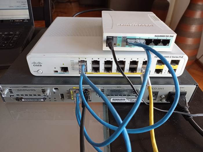
Utilizamos un router
Cisco y un Mikrotik para demostrar la compatibilidad
y poder observar las diferencias entre ambos en el intercambio de rutas.
1.- Verificación previa:
1.1.- Estado DOWN del link a
BGP-2:
1.2.- De rutas en router BGP-1 (Cisco):
Inicialmente en cada router
tendremos sólo las redes directamente conectadas.
BGP-1#sh ip route
Codes: C - connected, S - static, R - RIP, M - mobile, B - BGP
D - EIGRP, EX - EIGRP external, O - OSPF, IA -
OSPF inter area
N1 - OSPF NSSA external type
1, N2 - OSPF NSSA external type 2
E1 - OSPF external type 1,
E2 - OSPF external type 2
i
- IS-IS, su - IS-IS summary, L1 - IS-IS level-1, L2 -
IS-IS level-2
ia
- IS-IS inter area, * - candidate default, U - per-user static route
o - ODR, P - periodic
downloaded static route
Gateway of last resort is not set
190.0.0.0/24 is subnetted, 1 subnets
C 190.0.0.0 is directly
connected, FastEthernet0/0 (segmento del peering BGP)
181.0.0.0/24 is subnetted, 3 subnets
C 181.0.1.0 is directly connected,
FastEthernet0/1.1811 (sólo
las redes conectadas)
C 181.0.3.0 is directly connected, FastEthernet0/1.1813
C 181.0.2.0 is directly connected,
FastEthernet0/1.1812
BGP-1#
1.3.- De rutas en router BGP-2 (Mikrotik):
[admin@BGP-2] > ip route print
Flags: X - disabled, A - active, D - dynamic,
C - connect, S - static, r
- rip, b - bgp, o - ospf, m
- mme,
B - blackhole, U - unreachable, P - prohibit
# DST-ADDRESS PREF-SRC GATEWAY DISTANCE
0 ADC 190.0.0.0/24 190.0.0.2 ether1 0 (segmento del peering BGP)
1 ADC
200.0.1.0/24 200.0.1.1 vlan201 0 (sólo
las redes conectadas)
2 ADC 200.0.2.0/24 200.0.2.1 vlan202 0
3 ADC 200.0.3.0/24 200.0.3.1 vlan203 0
[admin@BGP-2] >
2.- Conectamos el peer
190.0.0.2 (BGP-2 Mikrotik) a la red:
2.1.- Estado UP / LIS / LRN
del link a BGP-2:
2.2.- Estado UP / FWD del
link a BGP-2:
2.3.- Conectividad layer 2 entre peers:
Al ser dos peers
directamente conectados en el mismo segmento deberá resolverse el destino en layer 2 mediante la resolución ARP.
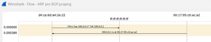
Detalle: para no mezclar
los temas, esta captura es independiente de la siguiente captura de tráfico
BGP.
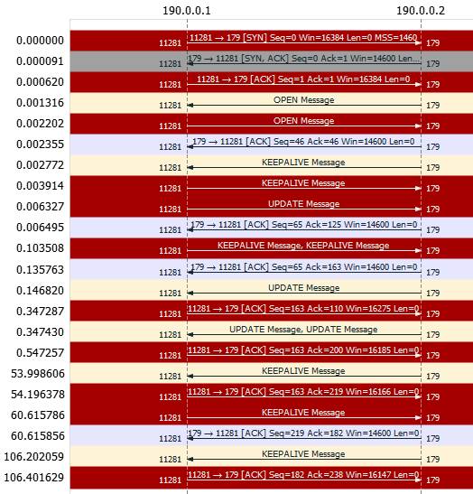
2.4.- Conectividad BGP:
2.4.1.- Aquí un breve
detalle de los estados BGP previos a la adyacencia, y sus respectivos paquetes
en la captura de Wireshark.
Idle:This is the first
state where BGP waits for a “start event”. The start event will initiates a TCP
connection to the remote BGP neighbor.
When successful, BGP moves to the Connect state. When it fails, it will
remain in the Idle state.
Connect: BGP is waiting for
the TCP three-way handshake to complete. When it is successful, it will
continue to the OpenSent state. (paquetes #1,2 y 3 en
Wireshark)
OpenSent: In this state BGP will be
waiting for an Open message from the remote BGP neighbor. (paquete #4 en
Wireshark)
The Open message will be checked for errors, If everything is OK then BGP
starts sending keepalive messages and resets its keepalive timer.
OpenConfirm: BGP waits for a keepalive
message from the remote BGP neighbor.
When we receive the keepalive, we can move to the established state and
the neighbor adjacency will be completed. (paquete
#7 en Wireshark)
Established: The BGP neighbor
adjacency is complete and the BGP routers will send update packets to exchange
routing information. (paquetes
#9, 13 y 15 en
Wireshark)
Every time we receive a keepalive or update message, the hold timer will
be resetted. (paquetes #17 y 21 en Wireshark)
2.4.2.- Logs en el router Cisco BGP-1:
BGP-1#debug ip bgp 190.0.0.2 updates
BGP updates debugging is on for neighbor 190.0.0.2 for address family:
IPv4 Unicast
BGP-1#debug ip routing
IP routing debugging is on
BGP-1#
May 2 15:50:12: %BGP-3-NOTIFICATION:
received from neighbor 190.0.0.2 6/7 (cease) 0 bytes (paquete #4 en
Wireshark)
May 2 15:50:44: %BGP-5-ADJCHANGE: neighbor 190.0.0.2 Up
May 2 15:50:44.135: BGP(0):
190.0.0.2 send UPDATE (format) 181.0.3.0/24, next 190.0.0.1, metric 0, path Local (paquete #9 en
Wireshark)
May 2 15:50:44.135: BGP(0):
190.0.0.2 send UPDATE (prepend, chgflags: 0x0) 181.0.2.0/24, next 190.0.0.1, metric 0, path Local
May 2 15:50:44.135: BGP(0):
190.0.0.2 send UPDATE (prepend, chgflags: 0x0) 181.0.1.0/24, next 190.0.0.1, metric 0, path Local
May 2 15:50:44.279: BGP(0):
190.0.0.2 rcvd UPDATE w/ attr:
nexthop 190.0.0.2, origin i,
path 65530
May 2 15:50:44.279: BGP(0):
190.0.0.2 rcvd 200.0.3.0/24 (paquete #13 en Wireshark)
May 2 15:50:44.279: RT: Try lookup
less specific 190.0.0.2/32, default 1
May 2 15:50:44.279: RT: Found
subnet on less specific 190.0.0.0/24
May 2 15:50:44.279: RT:
SET_LAST_RDB for 200.0.3.0/24
NEW rdb:
via 190.0.0.2
May 2
15:50:44.279: RT: add 200.0.3.0/24 via 190.0.0.2, bgp metric [20/0] (red agregada en la tabla de
enrutamiento)
May 2 15:50:44.279: RT: NET-RED
200.0.3.0/24
May 2 15:50:44.479: BGP(0):
190.0.0.2 rcvd UPDATE w/ attr:
nexthop 190.0.0.2, origin i,
path 65530 (paquete
#15 en Wireshark)
May 2 15:50:44.479: BGP(0):
190.0.0.2 rcvd 200.0.2.0/24
May 2 15:50:44.479: BGP(0):
190.0.0.2 rcvd UPDATE w/ attr:
nexthop 190.0.0.2, origin i,
path 65530 (paquete
#15 en Wireshark)
May 2 15:50:44.479: BGP(0):
190.0.0.2 rcvd 200.0.1.0/24
May 2 15:50:44.479: RT:
SET_LAST_RDB for 200.0.1.0/24
NEW rdb:
via 190.0.0.2
May 2
15:50:44.479: RT: add 200.0.1.0/24 via 190.0.0.2, bgp metric [20/0] (red agregada en la tabla de
enrutamiento)
May 2 15:50:44.479: RT: NET-RED
200.0.1.0/24
May 2 15:50:44.479: RT:
SET_LAST_RDB for 200.0.2.0/24
NEW rdb:
via 190.0.0.2
May 2
15:50:44.479: RT: add 200.0.2.0/24 via 190.0.0.2, bgp metric [20/0] (red agregada en la tabla de
enrutamiento)
May 2 15:50:44.479: RT: NET-RED
200.0.2.0/24
BGP-1#
3.- Verificamos en
Wireshark:
Realizamos un port mirroring para reenviar el tráfico BGP a un Wireshark.
3.1.- Vista general de la
captura:
3.2.- Detalle de la sesión
TCP establecida:
3.3.- Detalle de los updates BGP en texto plano:
Frame 9: 114 bytes on wire (912
bits), 114 bytes captured (912 bits)
Ethernet II, Src:
00:17:95:c0:ac:a2, Dst: d4:ca:6d:a4:2e:22 (capa
2 del modelo OSI)
Internet Protocol Version 4, Src: 190.0.0.1, Dst: 190.0.0.2 (capa
3 del modelo OSI)
Transmission Control Protocol, Src Port: 11281, Dst Port: 179, Seq: 65, Ack: 65, Len: 60 (capa 4 del modelo OSI)
Border Gateway Protocol - UPDATE Message (capa
7 del modelo OSI)
Marker: ffffffffffffffffffffffffffffffff
Length: 60
Type: UPDATE Message (2)
Withdrawn Routes Length: 0
Total Path Attribute Length: 25
Path attributes
Path Attribute - ORIGIN:
IGP
Path Attribute - AS_PATH: 65531
Path Attribute - NEXT_HOP: 190.0.0.1
Path Attribute - MULTI_EXIT_DISC: 0 (este atributo no lo informa el router Mikrotik)
Network Layer Reachability Information (NLRI)
181.0.3.0/24
181.0.2.0/24
181.0.1.0/24
Frame 13: 99 bytes on wire
(792 bits), 99 bytes captured (792 bits)
Ethernet II, Src: d4:ca:6d:a4:2e:22, Dst: 00:17:95:c0:ac:a2
Internet Protocol Version 4, Src: 190.0.0.2, Dst: 190.0.0.1
Transmission Control Protocol, Src Port: 179, Dst Port: 11281, Seq: 65, Ack: 163, Len: 45
Border Gateway Protocol - UPDATE Message
Marker: ffffffffffffffffffffffffffffffff
Length: 45
Type: UPDATE Message (2)
Withdrawn Routes Length: 0
Total Path Attribute Length: 18
Path attributes
Path Attribute - ORIGIN:
IGP
Path Attribute - AS_PATH: 65530
Path Attribute - NEXT_HOP: 190.0.0.2
Network Layer Reachability
Information (NLRI)
200.0.3.0/24
Frame 15: 144 bytes on wire
(1152 bits), 144 bytes captured (1152 bits)
Ethernet II, Src: d4:ca:6d:a4:2e:22, Dst: 00:17:95:c0:ac:a2
Internet Protocol Version 4, Src: 190.0.0.2, Dst: 190.0.0.1
Transmission Control Protocol, Src Port: 179, Dst Port: 11281, Seq: 110, Ack: 163, Len: 90
Border Gateway Protocol - UPDATE Message
Marker: ffffffffffffffffffffffffffffffff
Length: 45
Type: UPDATE Message (2)
Withdrawn Routes Length: 0
Total Path Attribute Length: 18
Path attributes
Path Attribute - ORIGIN:
IGP
Path Attribute - AS_PATH: 65530
Path Attribute - NEXT_HOP: 190.0.0.2
Network Layer Reachability Information
(NLRI)
200.0.2.0/24
Border Gateway Protocol - UPDATE Message
Marker: ffffffffffffffffffffffffffffffff
Length: 45
Type: UPDATE Message (2)
Withdrawn Routes Length: 0
Total Path Attribute Length: 18
Path attributes
Path Attribute - ORIGIN:
IGP
Path Attribute - AS_PATH: 65530
Path Attribute - NEXT_HOP: 190.0.0.2
Network Layer Reachability
Information (NLRI)
200.0.1.0/24
4.- Verificación de adyancencias
BGP:
4.1.- En el router Cisco:
BGP-1#sh ip bgp neighbors
BGP neighbor is 190.0.0.2, remote
AS 65530, external link
BGP version 4, remote router ID
190.0.0.2
BGP state = Established, up for 00:00:17
Last read 00:00:17, last write
00:00:17, hold time is 180, keepalive interval is 60 seconds
Neighbor capabilities:
(el resto queda como irrelevante
porque sólo analizamos el establecimiento de la sesión BGP)
Route refresh: advertised and received(old & new)
Address family IPv4 Unicast:
advertised and received
--- resumido
/ omitido ---
BGP-1#
4.2.- En el router Mikrotik:
[admin@BGP-2] > routing bgp peer print detail
Flags: X - disabled, E - established
0 E name="190.0.0.1" instance=default remote-address=190.0.0.1 remote-as=65531
tcp-md5-key="" nexthop-choice=default multihop=no
route-reflect=no
hold-time=3m ttl=255 in-filter="" out-filter=""
address-families=ip
default-originate=never
remove-private-as=no as-override=no passive=no
use-bfd=no
[admin@BGP-2] >
5.- Verificación en la tabla
de enrutamiento:
5.1.- En el router Cisco:
BGP-1#sh ip route
Codes: C - connected, S - static, R - RIP, M - mobile, B - BGP
D - EIGRP, EX - EIGRP
external, O - OSPF, IA - OSPF inter area
N1 - OSPF NSSA external type
1, N2 - OSPF NSSA external type 2
E1 - OSPF external type 1,
E2 - OSPF external type 2
i
- IS-IS, su - IS-IS summary, L1 - IS-IS level-1, L2 -
IS-IS level-2
ia
- IS-IS inter area, * - candidate default, U - per-user static route
o - ODR, P - periodic
downloaded static route
Gateway of last resort is not set
B 200.0.1.0/24 [20/0] via
190.0.0.2, 00:00:27 (no
pude encontrar el criterio de por qué está en este orden)
190.0.0.0/24 is subnetted,
1 subnets
C 190.0.0.0 is directly
connected, FastEthernet0/0
B 200.0.2.0/24 [20/0] via 190.0.0.2, 00:00:27
B 200.0.3.0/24 [20/0] via 190.0.0.2, 00:00:28
181.0.0.0/24 is subnetted, 3 subnets
C 181.0.1.0 is directly
connected, FastEthernet0/1.1811
C 181.0.3.0 is directly
connected, FastEthernet0/1.1813
C 181.0.2.0 is directly
connected, FastEthernet0/1.1812
BGP-1#
5.2.- En el router Mikrotik:
[admin@BGP-2] > ip route print
Flags: X - disabled, A - active, D - dynamic,
C - connect, S - static, r - rip, b - bgp,
o - ospf, m - mme,
B - blackhole, U - unreachable, P - prohibit
# DST-ADDRESS PREF-SRC GATEWAY DISTANCE
0 ADb 181.0.1.0/24
190.0.0.1 20
1 ADb 181.0.2.0/24 190.0.0.1 20
2 ADb 181.0.3.0/24
190.0.0.1 20
3 ADC 190.0.0.0/24 190.0.0.2 ether1 0
4 ADC 200.0.1.0/24 200.0.1.1 vlan201 0
5 ADC 200.0.2.0/24 200.0.2.1 vlan202 0
6 ADC 200.0.3.0/24 200.0.3.1 vlan203 0
[admin@BGP-2] >
6.- Tabla BGP en el router Cisco:
Los routers Cisco tienen
una tabla exclusivamente de BGP para determinar la mejor ruta a un destino, y
que luego será publicada en la tabla de enrutamiento (punto 5.1.)
si es que no existen rutas al mismo destino con
distancia administrativa mas baja (mejor AD), tales
como rutas estáticas o de otros protocolos de enrutamiento (con mejor AD).
BGP-1#sh ip bgp
BGP table version is 25, local router ID is 190.0.0.1
Status codes: s suppressed, d damped, h history, * valid, > best, i - internal,
r RIB-failure, S
Stale
Origin codes: i - IGP, e - EGP, ? - incomplete
Network Next Hop Metric LocPrf
Weight Path
*> 181.0.1.0/24 0.0.0.0 0 32768 i
*> 181.0.2.0/24 0.0.0.0 0 32768 i
*> 181.0.3.0/24 0.0.0.0 0 32768 i
*> 200.0.1.0 190.0.0.2 0 65530 I (AS de
tránsito para alcanzar el destino)
*> 200.0.2.0 190.0.0.2 0 65530 i
*> 200.0.3.0 190.0.0.2 0 65530 i
BGP-1#
7.- Configuración de los
equipos:
7.1.- Cisco:
BGP-1#sh runn (sólo lo más relevante)
Building configuration...
Current configuration : 1614 bytes
!
hostname BGP-1
!
interface FastEthernet0/0
ip
address 190.0.0.1 255.255.255.0 (segmento
de peering BGP)
!
interface FastEthernet0/1
no ip
address
!
interface FastEthernet0/1.1811
encapsulation dot1Q 1811
ip
address 181.0.1.1 255.255.255.0
!
interface FastEthernet0/1.1812
encapsulation dot1Q 1812
ip
address 181.0.2.1 255.255.255.0
!
interface FastEthernet0/1.1813
encapsulation dot1Q 1813
ip
address 181.0.3.1 255.255.255.0
!
router bgp 65531
no synchronization
bgp
log-neighbor-changes
network 181.0.1.0 mask
255.255.255.0
network 181.0.2.0 mask
255.255.255.0
network 181.0.3.0 mask
255.255.255.0
neighbor 190.0.0.2 remote-as 65530
no auto-summary
!
end
BGP-1#
7.2.- Mikrotik:
[admin@BGP-2] > /export
(sólo lo más relevante)
/interface vlan
add interface=ether2 name=vlan201 vlan-id=201
add interface=ether2 name=vlan202 vlan-id=202
add interface=ether2 name=vlan203 vlan-id=203
/ip address
add address=190.0.0.2/24 interface=ether1 network=190.0.0.0 (segmento de peering BGP)
add address=200.0.1.1/24 interface=vlan201 network=200.0.1.0
add address=200.0.2.1/24 interface=vlan202 network=200.0.2.0
add address=200.0.3.1/24 interface=vlan203 network=200.0.3.0
/routing bgp network
add network=200.0.1.0/24
add network=200.0.2.0/24
add network=200.0.3.0/24
/routing bgp peer
add name=190.0.0.1 remote-address=190.0.0.1 remote-as=65531
/system identity
set name=BGP-2
[admin@BGP-2] >
(2023) Tales for stoic
people…
Rosario, Argentina