Analizando la polarización CEF
Fecha: 17 y 18 de
agosto del 2023
Escenario
Este laboratorio analiza cómo la polarización de
Cisco Express Forwarding (CEF) puede causar un uso no óptimo de las
rutas redundantes a una red de destino. La
polarización CEF es el efecto cuando el algoritmo hash de CEF elige una ruta
determinada y las rutas redundantes permanecen
completamente sin utilizar.
Este laboratorio no describe ni analiza en
detalle CEF, pero lo baja al mundo real para poder darle performance a nuestra
infraestructura intentando balancear la carga de
los enlaces redundantes.

También analiza de como dependiendo del sistema
operativo, una prueba trace para determinar el uso de los enlaces
nos puede llevar a una conclusión errónea de que
enlaces se están utilizando, y cuál sería la verificación ideal.
Todas las decisiones analizadas son de izquierda
a derecha y no evaluamos el retorno ni el comportamiento agregado
del HSRP que también influye (bastante) en el
flujo de tráfico en general.
1.- Sobre rutas, CEF y la
polarización:
En CCNA aprendemos que cada paquete es comparado
contra una red destino en la tabla de enrutamiento (con rutas estáticas
o aprendidas por protocolos como BGP, EIGRP u
OSPF y la mejor coincidencia (la mayor cantidad de bits) es la ruta indicada
para
ese destino, entonces el paquete se “va del
router” mediante el próximo salto (next-hop).
Pero esto no es siempre así…
Puede que ocurra con el primer paquete que llegue
al router, pero en el segundo al mismo destino, probablemente el router utilice
CEF y su tabla FIB (Forward Information Base) que
es un caché donde la búsqueda y comparación es a mas alta velocidad, lo cual
genera mayor performance.
Para alcanzar en next-hop tenemos las búsquedas
recurrentes y la tabla ARP, pero también existe otra tabla de adyacencias, en
la
cual ya se encuentran listos los datos necesarios
para armar la trama (con el paquete IP como payload) de forma mas rápida y ser
transmitida con la menor latencia posible.
Pero a veces pueden haber rutas redundantes de
igual coste al mismo destino y la decisión acerca de cuál de los dos links se
utiliza
(o si se utilizan los dos balanceando carga) es
tomada por un algoritmo de hash parte de CEF que mencionamos antes.
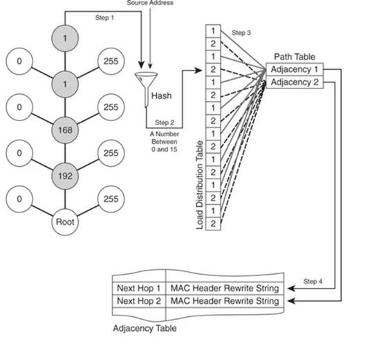
De forma predeterminada, la IP de origen (SIP) y
la IP de destino (DIP) se utilizan como parámetros en el algoritmo hash.
Cuando sólo hay dos trayectos, el switch L3 /
router realiza una operación OR exclusiva (XOR) en los bits de orden inferior
(un bit
cuando se debe seleccionar uno de dos enlaces,
dos bits para 3-4 links, etc.) del SIP y DIP.
La operación XOR del mismo SIP y DIP siempre da
como resultado el uso del mismo link, esto es la polarización CEF.
Fuente: www.cisco.com
Correlación de las tablas involucradas en el
forwarding, la tabla de adyacencias tiene listas las MAC de destino y origen
y el tipo de payload dependiendo de la interface
de salida (ver punto 3.4.).

2.- Evitando la polarización
CEF:
Existen algunos métodos para evitar la
polarización CEF, los cuales se deben configurar manualmente y las opciones
son:
Original algorithm--The original
Cisco Express Forwarding load-balancing algorithm produces distortions in load
sharing
across multiple routers because the same
algorithm was used on every router. Depending on your network environment,
you should select either the universal algorithm
(default) or the tunnel algorithm instead.
Universal algorithm--The universal
load-balancing algorithm allows each router on the network to make a different
load
sharing decision for each source-destination
address pair, which resolves load-sharing imbalances. The router is set to
perform universal load sharing by default.
Tunnel algorithm--The tunnel
algorithm is designed to balance the per-packet load when only a few source and
destination
pairs are involved.
Include-ports algorithm--The
include-ports algorithm allows you to use the Layer 4 source and destination
ports as part of
the load-balancing decision. This method benefits
traffic streams running over equal cost paths that are not load shared
because the majority of the traffic is between
peer addresses that use different port numbers, such as Real-Time Protocol
(RTP) streams. The include-ports algorithm is
available in Cisco IOS Release 12.4(11)T and later releases.
Fuente: cisco.com
Debemos tener en cuenta
que si elegimos balance por paquete (Tunnel algorithm), los enlaces serán
utilizados 1 paquete
a la vez tipo
round-robin y eso podría generar cierta asimetría debido a leves retardos en
los enlaces por carga si tenemos
tráfico de tamaño
variable y la recepción a destiempo de los paquetes/segmentos lo que en caso de
TCP el host final debería
reordenarlos generando
más carga de CPU y/o latencia.

3.- Verificación inicial:
3.1.- Tabla de enrutamiento:
Router-A#sh ip route
Codes: L - local, C - connected, S - static, R -
RIP, M - mobile, B - BGP
D -
EIGRP, EX - EIGRP external, O - OSPF, IA - OSPF inter area
N1 -
OSPF NSSA external type 1, N2 - OSPF NSSA external type 2
E1 -
OSPF external type 1, E2 - OSPF external type 2
i -
IS-IS, su - IS-IS summary, L1 - IS-IS level-1, L2 - IS-IS level-2
ia -
IS-IS inter area, * - candidate default, U - per-user static route
o -
ODR, P - periodic downloaded static route, H - NHRP, l - LISP
a -
application route
+ -
replicated route, % - next hop override
Gateway of last resort is not set
10.0.0.0/8 is variably subnetted, 4 subnets, 2
masks
C
10.0.0.0/30 is directly connected, Vlan100
L
10.0.0.1/32 is directly connected, Vlan100
C
10.0.0.4/30 is directly connected, Vlan104
L
10.0.0.5/32 is directly connected, Vlan104
192.168.0.0/24 is variably subnetted, 2 subnets, 2 masks
C
192.168.0.0/24 is directly connected, Vlan1
L
192.168.0.1/32 is directly connected, Vlan1
O 192.168.1.0/24 [110/2] via 10.0.0.6, 00:04:25, Vlan104
[110/2] via 10.0.0.2, 00:37:30, Vlan100
Router-A#
3.2.- Tabla CEF:
Router-A#sh ip cef
Prefix Next Hop Interface
0.0.0.0/0 no route
0.0.0.0/8 drop
0.0.0.0/32 receive
10.0.0.0/30 attached Vlan100
10.0.0.0/32 receive Vlan100
10.0.0.1/32 receive Vlan100
10.0.0.2/32 attached Vlan100
10.0.0.3/32 receive Vlan100
10.0.0.4/30 attached Vlan104
10.0.0.4/32 receive Vlan104
10.0.0.5/32 receive Vlan104
10.0.0.6/32 attached Vlan104
10.0.0.7/32
receive Vlan104
192.168.0.0/24 attached Vlan1
192.168.0.0/32 receive Vlan1
192.168.0.1/32 receive Vlan1
192.168.0.10/32 attached Vlan1
192.168.0.255/32
receive Vlan1
192.168.1.0/24 10.0.0.2 Vlan100
10.0.0.6 Vlan104
224.0.0.0/4 drop
224.0.0.0/24 receive
240.0.0.0/4 drop
255.255.255.255/32 receive
Router-A#
Router-A#sh ip cef 192.168.1.0
192.168.1.0/24
nexthop
10.0.0.2 Vlan100
nexthop
10.0.0.6 Vlan104
Router-A#
Router-A#sh ip cef 192.168.1.0 detail
192.168.1.0/24, epoch 0, per-destination sharing
nexthop
10.0.0.2 Vlan100
nexthop
10.0.0.6 Vlan104
Router-A#
Router-A#sh ip cef 192.168.1.0
internal
192.168.1.0/24, epoch 0, RIB[I], refcount 5,
per-destination sharing
sources:
RIB
feature
space:
IPRM:
0x00028000
ifnums:
Vlan100(11):
10.0.0.2
Vlan104(12): 10.0.0.6
path
0EDB1EBC, path list 02C72170, share 1/1, type attached nexthop, for IPv4
nexthop
10.0.0.2 Vlan100, adjacency IP adj out of Vlan100, addr 10.0.0.2 01944880
path
0EDB1F2C, path list 02C72170, share 0/1, type attached nexthop, for IPv4
nexthop
10.0.0.6 Vlan104, adjacency IP adj out of Vlan104, addr 10.0.0.6 019449E0
output
chain:
loadinfo 018C1E2C, per-session, 2 choices, flags 0083, 5 locks
flags:
Per-session, for-rx-IPv4, 2buckets
2 hash
buckets
<
0 > IP adj out of Vlan100, addr 10.0.0.2 01944880
<
1 > IP adj out of Vlan104, addr 10.0.0.6 019449E0
Subblocks:
None
Router-A#
3.3.- Tabla de ARP:
Router-A#sh arp
Protocol
Address Age (min) Hardware Addr Type
Interface
Internet
10.0.0.1 - cc46.d62b.5a54 ARPA
Vlan100 (link
Router-A –> Router-B)
Internet
10.0.0.2 18 0017.95c0.aca2 ARPA
Vlan100 (Router-B)
Internet
10.0.0.5 - cc46.d62b.5a54 ARPA
Vlan104 (link
Router-A –> Router-C)
Internet
10.0.0.6 17 7081.05b5.7782 ARPA
Vlan104 (Router-C)
Internet
192.168.0.1 - cc46.d62b.5a54 ARPA
Vlan1 (red LAN)
Internet
192.168.0.10 4
001b.38fe.8ac7 ARPA Vlan1
Internet
192.168.0.11 1 001b.38fe.8ac7 ARPA
Vlan1
Router-A#
3.4.- Tabla de adyacencias:
Router-A#sh adjacency detail (la tabla de adyacencias L2/L3)
Protocol Interface Address
IP Vlan1 192.168.0.10(7) (la PC de origen)
3 packets,
162 bytes
epoch 0
sourced in
sev-epoch 2
Encap length
14
001B38FE8AC7CC46D62B5A540800
| | |
MAC destino MAC origen campo type del payload
ARP
IP
Vlan1
192.168.0.11(7) (la
PC de origen con 2da IP)
4 packets,
216 bytes
epoch 0
sourced in sev-epoch
2
Encap length
14
001B38FE8AC7CC46D62B5A540800
ARP
IP
Vlan100 10.0.0.2(10) (el link a Router-B)
5 packets, 370 bytes
epoch 0
sourced in
sev-epoch 1
Encap length
14
001795C0ACA2CC46D62B5A540800
ARP
IP
Vlan104 10.0.0.6(10) (el link a Router-C)
3 packets,
222 bytes
epoch 0
sourced in
sev-epoch 2
Encap
length 14
708105B57782CC46D62B5A540800
ARP
Router-A#
4.- Prueba inicial:
4.1.- Verificamos el origen
del tráfico en el Router-C:
Al verificar el origen del tráfico en el router
final que entregará el paquete al destino, debemos interpretar que la IP es la
192.168.0.10,
pero la MAC origen será la del Router-B (o el
Router-C), que es quien entregará la trama/paquete a la IP destino
192.168.1.10.
Para darnos una idea de donde recibirá la
trama/paquete la IP destino veamos el siguiente esquema:

Router-C#sh arp
Protocol
Address Age (min) Hardware Addr Type
Interface
Internet
10.0.0.5 48 cc46.d62b.5a54 ARPA
Vlan104
Internet
10.0.0.6 - 7081.05b5.7782 ARPA
Vlan104
Internet
192.168.1.1 10 0000.0c07.ac01 ARPA
Vlan1
Internet
192.168.1.2 10 0017.95c0.aca3 ARPA
Vlan1 (Router-B)
Internet
192.168.1.3 - 7081.05b5.7782 ARPA
Vlan1 (Router-C)
Internet
192.168.1.10 18 001b.387e.f171 ARPA
Vlan1
Router-C#
4.2.- Se genera tráfico ICMP
(sin
ports origen ni destino):
root@ernesto:~# ping 192.168.1.10
PING 192.168.1.10 (192.168.1.10) 56(84) bytes of
data.
64 bytes from 192.168.1.10: icmp_seq=1 ttl=126
time=2.88 ms
64 bytes from 192.168.1.10: icmp_seq=2 ttl=126
time=1.10 ms
64 bytes from 192.168.1.10: icmp_seq=3 ttl=126
time=1.08 ms
64 bytes from 192.168.1.10: icmp_seq=4 ttl=126
time=1.08 ms
4.3.- Verificamos en la PC
destino:
Mediante la MAC origen, podemos determinar que el
tráfico llega a través del Router-C, que esta en caché
CEF para las IP origen y destino de esta prueba.

Frame 1: 98 bytes on
wire (784 bits), 98 bytes captured (784 bits) on interface id 0 (via Router-C)
Ethernet II, Src: 70:81:05:b5:77:82, Dst:
00:1b:38:7e:f1:71
Internet Protocol Version 4, Src: 192.168.0.10,
Dst: 192.168.1.10
Internet Control Message Protocol
Frame 3: 98 bytes on
wire (784 bits), 98 bytes captured (784 bits) on interface id 0 (via Router-C)
Ethernet II, Src: 70:81:05:b5:77:82, Dst:
00:1b:38:7e:f1:71
Internet Protocol Version 4, Src: 192.168.0.10,
Dst: 192.168.1.10
Internet Control Message Protocol
Frame 5: 98 bytes on
wire (784 bits), 98 bytes captured (784 bits) on interface id 0 (via Router-C)
Ethernet II, Src: 70:81:05:b5:77:82, Dst:
00:1b:38:7e:f1:71
Internet Protocol Version 4, Src: 192.168.0.10,
Dst: 192.168.1.10
Internet Control Message Protocol
4.4.- Se genera tráfico TCP (con ports
origen aleatorio y destino fijo):
En este caso el port destino es siempre el port
23, que se fuerza a que resulte en refused para agilizar los reintentos.
root@ernesto:~# telnet 192.168.1.10
Trying 192.168.1.10...
telnet: Unable to connect to remote host:
Connection refused
root@ernesto:~# telnet 192.168.1.10
Trying 192.168.1.10...
telnet: Unable to connect to remote host: Connection
refused
root@ernesto:~# telnet 192.168.1.10
Trying 192.168.1.10...
telnet: Unable to connect to remote host:
Connection refused
root@ernesto:~#
4.5.- Verificamos en la PC
destino:

Frame 1: 74 bytes on
wire (592 bits), 74 bytes captured (592 bits) on interface id 0 (via Router-C)
Ethernet II, Src: 70:81:05:b5:77:82, Dst:
00:1b:38:7e:f1:71
Internet Protocol Version 4, Src: 192.168.0.10,
Dst: 192.168.1.10
Transmission Control Protocol, Src Port: 34568,
Dst Port: 23, Seq: 0, Len: 0
Frame 2: 74 bytes on
wire (592 bits), 74 bytes captured (592 bits) on interface id 0 (via Router-C)
Ethernet II, Src: 70:81:05:b5:77:82, Dst:
00:1b:38:7e:f1:71
Internet Protocol Version 4, Src: 192.168.0.10,
Dst: 192.168.1.10
Transmission Control Protocol, Src Port: 34570,
Dst Port: 23, Seq: 0, Len: 0
Frame 3: 74 bytes on
wire (592 bits), 74 bytes captured (592 bits) on interface id 0 (via Router-C)
Ethernet II, Src: 70:81:05:b5:77:82, Dst:
00:1b:38:7e:f1:71
Internet Protocol Version 4, Src: 192.168.0.10,
Dst: 192.168.1.10
Transmission Control Protocol, Src Port: 34572,
Dst Port: 23, Seq: 0, Len: 0

4.6.- Verificamos en el
Router-A:
Router-A#sh ip cef exact-route
192.168.0.10 192.168.1.11
192.168.0.10 -> 192.168.1.11 => IP adj out
of Vlan104, addr 10.0.0.6 (via
el Router-C)
Router-A#
5.- Se modifica el load
sharing teniendo en cuenta ports origen y destino:
Aquí le agregamos una variable mas a la
posibilidad de que CEF utilice el segundo camino entre Router-A y Router-B
utilizando además de las IP origen y destino que
son fijas, información de capa 4 tal como puertos de origen (variable)
y puerto destino (en estas pruebas al pegarle al
TCP 23 en un valor fijo).
5.1.- Configuramos en el
Router-A:
Router-A#conf t
Enter configuration commands, one per line. End with CNTL/Z.
Router-A(config)#ip cef load-sharing
algorithm ?
include-ports Algorithm that
includes layer 4 ports
original Original
algorithm
tunnel Algorithm for
use in tunnel only environments
universal Algorithm for use
in most environments
Router-A(config)#ip cef load-sharing
algorithm include-ports source destination
Router-A(config)#end
Router-A#
5.2.- Verificamos:
Router-A#sh runn | inc cef (no hay un comando que indique algo más puntual)
ip cef
ip cef load-sharing algorithm include-ports
source destination
Router-A#
5.3.- Se genera tráfico ICMP
(sin
ports origen ni destino):
root@ernesto:~# ping 192.168.1.10
PING 192.168.1.10 (192.168.1.10) 56(84) bytes of
data.
64 bytes from 192.168.1.10: icmp_seq=1 ttl=126
time=2.88 ms
64 bytes from 192.168.1.10: icmp_seq=2 ttl=126
time=1.10 ms
64 bytes from 192.168.1.10: icmp_seq=3 ttl=126
time=1.08 ms
64 bytes from 192.168.1.10: icmp_seq=4 ttl=126
time=1.08 ms
5.4- Verificamos en la PC
destino:
En la captura de Wireshark de la PC destino
podemos observar que los pings utilizan ICMP, y al no tener
puertos como TCP, el load-sharing de CEF
utilizará siempre la IP destino como referencia y utilizando
siempre el mismo camino.

Frame 1: 74 bytes on
wire (592 bits), 74 bytes captured (592 bits) on interface id 0 (via Router-C)
Ethernet II, Src: 70:81:05:b5:77:82, Dst:
00:1b:38:7e:f1:71
Internet Protocol Version 4, Src: 192.168.0.10,
Dst: 192.168.1.10
Transmission Control Protocol, Src Port: 34568,
Dst Port: 23, Seq: 0, Len: 0
Frame 2: 74 bytes on
wire (592 bits), 74 bytes captured (592 bits) on interface id 0 (via Router-C)
Ethernet II, Src: 70:81:05:b5:77:82, Dst:
00:1b:38:7e:f1:71
Internet Protocol Version 4, Src: 192.168.0.10,
Dst: 192.168.1.10
Transmission Control Protocol, Src Port: 34570,
Dst Port: 23, Seq: 0, Len: 0
Frame 3: 74 bytes on
wire (592 bits), 74 bytes captured (592 bits) on interface id 0 (via Router-C)
Ethernet II, Src: 70:81:05:b5:77:82, Dst:
00:1b:38:7e:f1:71
Internet Protocol Version 4, Src: 192.168.0.10,
Dst: 192.168.1.10
Transmission Control Protocol, Src Port: 34572,
Dst Port: 23, Seq: 0, Len: 0
5.5.- Se genera tráfico TCP (con ports
origen aleatorio y destino fijo):
En este caso el port destino es siempre el port
23, que se fuerza a que resulte en refused para agilizar los reintentos.
root@ernesto:~# telnet 192.168.1.10
Trying 192.168.1.10...
telnet: Unable to connect to remote host:
Connection refused
root@ernesto:~# telnet 192.168.1.10
Trying 192.168.1.10...
telnet: Unable to connect to remote host:
Connection refused
root@ernesto:~# telnet 192.168.1.10
Trying 192.168.1.10...
telnet: Unable to connect to remote host:
Connection refused
root@ernesto:~# telnet 192.168.1.10
Trying 192.168.1.10...
telnet: Unable to connect to remote host:
Connection refused
root@ernesto:~#
5.6.- Verificamos en la PC
destino:
En la captura de Wireshark de la PC destino
podemos observar que la MAC origen se mantiene siempre en Router-B y
Aunque los ports origen TCP varían, curiosamente
siempre con números pares, al mantenerse la IP y puerto destino,
CEF determina que debe utilizar siempre el mismo
camino en caché, en este caso también es el Router-C.

Frame 1: 74 bytes on
wire (592 bits), 74 bytes captured (592 bits) on interface id 0 (via Router-C)
Ethernet II, Src: 70:81:05:b5:77:82, Dst:
00:1b:38:7e:f1:71
Internet Protocol Version 4, Src: 192.168.0.10,
Dst: 192.168.1.10
Transmission Control Protocol, Src Port: 35148, Dst Port: 23, Seq: 0, Len: 0
Frame 2: 74 bytes on
wire (592 bits), 74 bytes captured (592 bits) on interface id 0 (via Router-C)
Ethernet II, Src: 70:81:05:b5:77:82, Dst:
00:1b:38:7e:f1:71
Internet Protocol Version 4, Src: 192.168.0.10,
Dst: 192.168.1.10
Transmission Control Protocol, Src Port: 35150, Dst Port: 23, Seq: 0, Len: 0
Frame 3: 74 bytes on
wire (592 bits), 74 bytes captured (592 bits) on interface id 0 (via Router-C)
Ethernet II, Src: 70:81:05:b5:77:82, Dst: 00:1b:38:7e:f1:71
Internet Protocol Version 4, Src: 192.168.0.10,
Dst: 192.168.1.10
Transmission Control Protocol, Src Port: 35152, Dst Port: 23, Seq: 0, Len: 0
Frame 4: 74 bytes on
wire (592 bits), 74 bytes captured (592 bits) on interface id 0 (via Router-C)
Ethernet II, Src: 70:81:05:b5:77:82, Dst:
00:1b:38:7e:f1:71
Internet Protocol Version 4, Src: 192.168.0.10,
Dst: 192.168.1.10
Transmission Control Protocol, Src Port: 35154, Dst Port: 23, Seq: 0, Len: 0

6.- Modificamos la
configuración del balanceo CEF:
En la siguiente prueba, se implementa el algoritmo
que utiliza las IP origen y destino y sólo el puerto origen de layer 4,
lo cual es lo único que varía debido a que le
apuntamos siempre al puerto TCP 23 del Telnet y que puede influír en la
toma de decisión de rutas. En el mundo real, si se
consume mas un port que otro de un server en la red destino puede
llegara ocurrir este desbalance, por lo que
deberíamos optar por un valor algo más variable como el puero de origen.

6.1.- Configuramos Router-A:
Router-A#conf t
Enter configuration commands, one per line. End with CNTL/Z.
Router-A(config)#ip cef load-sharing
algorithm include-ports source
Router-A(config)#end
Router-A#
6.2.- Verificamos:
Router-A#sh runn | inc ip cef
ip cef
ip cef load-sharing algorithm include-ports
source
Router-A#
6.3.- Se genera tráfico ICMP
(sin
ports origen ni destino):
root@ernesto:~# ping 192.168.1.10
PING 192.168.1.10 (192.168.1.10) 56(84) bytes of
data.
64 bytes from 192.168.1.10: icmp_seq=1 ttl=126
time=2.88 ms
64 bytes from 192.168.1.10: icmp_seq=2 ttl=126
time=1.10 ms
64 bytes from 192.168.1.10: icmp_seq=3 ttl=126
time=1.08 ms
64 bytes from 192.168.1.10: icmp_seq=4 ttl=126
time=1.08 ms
6.4.- Verificamos en la PC
destino:
En la captura de Wireshark de la PC destino
podemos observar que los pings utilizan ICMP, y al no tener
puertos como TCP, el load-sharing de CEF
utilizará siempre la IP destino como referencia y utilizando
siempre el mismo camino.

Frame 1: 98 bytes on
wire (784 bits), 98 bytes captured (784 bits) on interface id 0 (via Router-B)
Ethernet II, Src: 00:17:95:c0:ac:a3, Dst:
00:1b:38:7e:f1:71
Internet Protocol Version 4, Src: 192.168.0.10,
Dst: 192.168.1.10
Internet Control Message Protocol
Frame 3: 98 bytes on
wire (784 bits), 98 bytes captured (784 bits) on interface id 0 (via Router-B)
Ethernet II, Src: 00:17:95:c0:ac:a3, Dst:
00:1b:38:7e:f1:71
Internet Protocol Version 4, Src: 192.168.0.10,
Dst: 192.168.1.10
Internet Control Message Protocol
Frame 5: 98 bytes on
wire (784 bits), 98 bytes captured (784 bits) on interface id 0 (via Router-B)
Ethernet II, Src: 00:17:95:c0:ac:a3, Dst:
00:1b:38:7e:f1:71
Internet Protocol Version 4, Src: 192.168.0.10,
Dst: 192.168.1.10
Internet Control Message Protocol

6.5.- Se genera tráfico TCP (con ports
origen aleatorio y port destino fijo):
root@ernesto:~# telnet 192.168.1.10
Trying 192.168.1.10...
telnet: Unable to connect to remote host:
Connection refused
root@ernesto:~# telnet 192.168.1.10
Trying 192.168.1.10...
telnet: Unable to connect to remote host:
Connection refused
root@ernesto:~# telnet 192.168.1.10
Trying 192.168.1.10...
telnet: Unable to connect to remote host:
Connection refused
root@ernesto:~# telnet 192.168.1.10
Trying 192.168.1.10...
telnet: Unable to connect to remote host:
Connection refused
root@ernesto:~#
6.6.- Verificamos en la PC
destino:
En la captura de Wireshark de la PC destino
podemos observar que las MAC origen se alternan entre Router-B y
Router-C y que los ports origen TCP también varían,
siempre con números pares lo que también nos hace pensar
que aunque sea par, el el bit LSB del hash
determina que se utilice un camino u otro.

Frame 1: 74 bytes on
wire (592 bits), 74 bytes captured (592 bits) on interface id 0 (via Router-C)
Ethernet II, Src: 70:81:05:b5:77:82, Dst:
00:1b:38:7e:f1:71
Internet Protocol Version 4, Src: 192.168.0.10,
Dst: 192.168.1.10
Transmission Control Protocol, Src Port: 35156, Dst Port: 23, Seq: 0, Len: 0
Frame 2: 74 bytes on
wire (592 bits), 74 bytes captured (592 bits) on interface id 0 (via Router-B)
Ethernet II, Src: 00:17:95:c0:ac:a3, Dst:
00:1b:38:7e:f1:71
Internet Protocol Version 4, Src: 192.168.0.10,
Dst: 192.168.1.10
Transmission Control Protocol, Src Port: 35158, Dst Port: 23, Seq: 0, Len: 0
Frame 3: 74 bytes on
wire (592 bits), 74 bytes captured (592 bits) on interface id 0 (via Router-C)
Ethernet II, Src: 70:81:05:b5:77:82, Dst:
00:1b:38:7e:f1:71
Internet Protocol Version 4, Src: 192.168.0.10,
Dst: 192.168.1.10
Transmission Control Protocol, Src Port: 35160, Dst Port: 23, Seq: 0, Len: 0
Frame 4: 74 bytes on
wire (592 bits), 74 bytes captured (592 bits) on interface id 0 (via Router-B)
Ethernet II, Src: 00:17:95:c0:ac:a3, Dst:
00:1b:38:7e:f1:71
Internet Protocol Version 4, Src: 192.168.0.10,
Dst: 192.168.1.10
Transmission Control Protocol, Src Port: 35162, Dst Port: 23, Seq: 0, Len: 0

7.- Pruebas con Traceroute
de Linux:
El Traceroute de Linux, a diferencia del Tracert
de Windows, por default utiliza UDP, por lo tanto utilizará puertos
de origen y destino para estas pruebas, lo que se
supone le agregará una variante a la toma de decisiones CEF.
7.1.- Generamos traceroutes:
root@ernesto:~# traceroute 192.168.1.10
traceroute to 192.168.1.10 (192.168.1.10), 30
hops max, 60 byte packets
1 gateway (192.168.0.1) 0.878 ms
0.916 ms 0.985 ms
2 10.0.0.2 (10.0.0.2) 1.342 ms
1.343 ms 1.768 ms
3 192.168.1.10 (192.168.1.10) 1.223 ms
1.286 ms 1.180 ms
root@ernesto:~#
root@ernesto:~# traceroute 192.168.1.10
traceroute to 192.168.1.10 (192.168.1.10), 30
hops max, 60 byte packets
1 gateway (192.168.0.1) 0.872 ms
0.913 ms 0.982 ms
2 10.0.0.6 (10.0.0.6) 1.380 ms 10.0.0.2 (10.0.0.2) 1.359 ms 10.0.0.6 (10.0.0.6) 1.699 ms
3 192.168.1.10 (192.168.1.10) 1.328 ms
1.250 ms 1.228 ms
root@ernesto:~#
root@ernesto:~# traceroute 192.168.1.10
traceroute to 192.168.1.10 (192.168.1.10), 30
hops max, 60 byte packets
1 gateway (192.168.0.1) 0.878 ms
0.916 ms 0.985 ms
2 10.0.0.2 (10.0.0.2) 1.342 ms
1.343 ms 1.768 ms
3 192.168.1.10 (192.168.1.10) 1.224 ms
1.266 ms 1.184 ms
root@ernesto:~#
7.2.- Verificamos en PC
destino:

Frame 1: 74 bytes on
wire (592 bits), 74 bytes captured (592 bits) on interface id 0
Ethernet II, Src: 00:17:95:c0:ac:a3, Dst:
00:1b:38:7e:f1:71
Internet Protocol Version 4, Src: 192.168.0.10,
Dst: 192.168.1.10
User Datagram Protocol, Src Port: 38819, Dst Port: 33440 (port
origen par vía Router-B)(1 de 10)
Data (32 bytes)
Frame 2: 74 bytes on
wire (592 bits), 74 bytes captured (592 bits) on interface id 0
Ethernet II, Src: 00:17:95:c0:ac:a3, Dst:
00:1b:38:7e:f1:71
Internet Protocol Version 4, Src: 192.168.0.10,
Dst: 192.168.1.10
User Datagram Protocol, Src Port: 37408, Dst Port: 33441 (port
origen impar vía Router-B)(1 de 10)
Data (32 bytes)
Frame 3: 74 bytes on
wire (592 bits), 74 bytes captured (592 bits) on interface id 0
Ethernet II, Src: 70:81:05:b5:77:82, Dst:
00:1b:38:7e:f1:71
Internet Protocol Version 4, Src: 192.168.0.10,
Dst: 192.168.1.10
User Datagram Protocol, Src Port: 42819, Dst Port: 33442 (port origen impar vía Router-C)(1
de 10)
Data (32 bytes)
Frame 4: 74 bytes on
wire (592 bits), 74 bytes captured (592 bits) on interface id 0
Ethernet II, Src: 00:17:95:c0:ac:a3, Dst:
00:1b:38:7e:f1:71
Internet Protocol Version 4, Src: 192.168.0.10,
Dst: 192.168.1.10
User Datagram Protocol, Src Port: 34611, Dst Port: 33444 (port
origen impar vía Router-C)(2 de 10)
Data (32 bytes)
Frame 5: 74 bytes on
wire (592 bits), 74 bytes captured (592 bits) on interface id 0
Ethernet II, Src: 70:81:05:b5:77:82, Dst:
00:1b:38:7e:f1:71
Internet Protocol Version 4, Src: 192.168.0.10,
Dst: 192.168.1.10
User Datagram Protocol, Src Port: 49108, Dst Port: 33443 (port
origen par vía Router-C)(1 de 10)
Data (32 bytes)
Frame 6: 74 bytes on
wire (592 bits), 74 bytes captured (592 bits) on interface id 0
Ethernet II, Src: 00:17:95:c0:ac:a3, Dst:
00:1b:38:7e:f1:71
Internet Protocol Version 4, Src: 192.168.0.10,
Dst: 192.168.1.10
User Datagram Protocol, Src Port: 48833, Dst Port: 33445 (port origen impar vía Router-B)(2
de 10)
Data (32 bytes)
Frame 7: 74 bytes on
wire (592 bits), 74 bytes captured (592 bits) on interface id 0
Ethernet II, Src: 70:81:05:b5:77:82, Dst:
00:1b:38:7e:f1:71
Internet Protocol Version 4, Src: 192.168.0.10,
Dst: 192.168.1.10
User Datagram Protocol, Src Port: 42742, Dst Port: 33446 (port origen par vía Router-C)(2
de 10)
Data (32 bytes)
Frame 8: 74 bytes on
wire (592 bits), 74 bytes captured (592 bits) on interface id 0
Ethernet II, Src: 00:17:95:c0:ac:a3, Dst:
00:1b:38:7e:f1:71
Internet Protocol Version 4, Src: 192.168.0.10,
Dst: 192.168.1.10
User Datagram Protocol, Src Port: 44399, Dst Port: 33447 (port origen impar vía Router-B)(3
de 10)
Data (32 bytes)
Frame 9: 74 bytes on
wire (592 bits), 74 bytes captured (592 bits) on interface id 0
Ethernet II, Src: 00:17:95:c0:ac:a3, Dst:
00:1b:38:7e:f1:71
Internet Protocol Version 4, Src: 192.168.0.10,
Dst: 192.168.1.10
User Datagram Protocol, Src Port: 52892, Dst Port: 33448 (port origen par vía Router-B)(2
de 10)
Data (32 bytes)
Frame 10: 74 bytes on
wire (592 bits), 74 bytes captured (592 bits) on interface id 0
Ethernet II, Src: 00:17:95:c0:ac:a3, Dst:
00:1b:38:7e:f1:71
Internet Protocol Version 4, Src: 192.168.0.10,
Dst: 192.168.1.10
User Datagram Protocol, Src Port: 46457, Dst Port: 33449 (port
origen impar vía Router-B)(4 de 10)
Data (32 bytes)
7.3.- Entonces tenemos:
Router-B
port origen par: 2 paquetes/tramas
Router-B
port origen impar: 4
Router-C
port origen par: 2
Router-C
port origen impar: 2
Total: 10 (6 via Router-B y 4 via Router-C o sea, 60/40)
8.- Pruebas Telnet a 2 IP
destino:
Se realizaron intentos de conexiones Telnet desde
un mismo origen a diferentes destinos, y se sacaron
estadísticas en una muestra de sólo 10 intentos y
nos dio 2 de 10 y 8 de 10.

8.1.- Generamos tráfico
Telnet:
root@ernesto:~# telnet 192.168.1.10
Trying 192.168.1.10...
telnet: Unable to connect to remote host:
Connection refused
root@ernesto:~#
root@ernesto:~# telnet 192.168.1.11
Trying 192.168.1.11...
telnet: Unable to connect to remote host:
Connection refused
root@ernesto:~#
root@ernesto:~# telnet 192.168.1.10
Trying 192.168.1.10...
telnet: Unable to connect to remote host:
Connection refused
root@ernesto:~#
root@ernesto:~# telnet 192.168.1.11
Trying 192.168.1.11...
telnet: Unable to connect to remote host:
Connection refused
root@ernesto:~#
8.2.- Verificamos en PC
destino:

Frame 1: 74 bytes on
wire (592 bits), 74 bytes captured (592 bits) on interface id 0 (vía Router-C)(1 de 10)
Ethernet II, Src: 70:81:05:b5:77:82, Dst:
00:1b:38:7e:f1:71
Internet Protocol Version 4, Src: 192.168.0.10,
Dst: 192.168.1.10
Transmission Control Protocol, Src Port: 33896,
Dst Port: 23, Seq: 0, Len: 0
Frame 2: 74 bytes on
wire (592 bits), 74 bytes captured (592 bits) on interface id 0 (vía Router-C)(2 de 10)
Ethernet II, Src: 70:81:05:b5:77:82, Dst:
00:1b:38:7e:f1:71
Internet Protocol Version 4, Src: 192.168.0.10,
Dst: 192.168.1.11
Transmission Control Protocol, Src Port: 42764,
Dst Port: 23, Seq: 0, Len: 0
Frame 3: 74 bytes on
wire (592 bits), 74 bytes captured (592 bits) on interface id 0 (vía Router-C)(3 de 10)
Ethernet II, Src: 70:81:05:b5:77:82, Dst:
00:1b:38:7e:f1:71
Internet Protocol Version 4, Src: 192.168.0.10,
Dst: 192.168.1.10
Transmission Control Protocol, Src Port: 33900,
Dst Port: 23, Seq: 0, Len: 0
Frame 4: 74 bytes on
wire (592 bits), 74 bytes captured (592 bits) on interface id 0 (vía Router-C)(4 de 10)
Ethernet II, Src: 70:81:05:b5:77:82, Dst:
00:1b:38:7e:f1:71
Internet Protocol Version 4, Src: 192.168.0.10,
Dst: 192.168.1.11
Transmission Control Protocol, Src Port: 42768,
Dst Port: 23, Seq: 0, Len: 0
Frame 5: 74 bytes on
wire (592 bits), 74 bytes captured (592 bits) on interface id 0 (vía Router-B)(1 de 10)
Ethernet II, Src: 00:17:95:c0:ac:a3, Dst:
00:1b:38:7e:f1:71
Internet Protocol Version 4, Src: 192.168.0.10,
Dst: 192.168.1.10
Transmission Control Protocol, Src Port: 33904,
Dst Port: 23, Seq: 0, Len: 0
Frame 6: 74 bytes on
wire (592 bits), 74 bytes captured (592 bits) on interface id 0 (vía Router-B)(2 de 10)
Ethernet II, Src: 00:17:95:c0:ac:a3, Dst:
00:1b:38:7e:f1:71
Internet Protocol Version 4, Src: 192.168.0.10,
Dst: 192.168.1.11
Transmission Control Protocol, Src Port: 42772,
Dst Port: 23, Seq: 0, Len: 0
Frame 7: 74 bytes on
wire (592 bits), 74 bytes captured (592 bits) on interface id 0 (vía Router-C)(5 de 10)
Ethernet II, Src: 70:81:05:b5:77:82, Dst:
00:1b:38:7e:f1:71
Internet Protocol Version 4, Src: 192.168.0.10,
Dst: 192.168.1.10
Transmission Control Protocol, Src Port: 33908,
Dst Port: 23, Seq: 0, Len: 0
Frame 8: 74 bytes on
wire (592 bits), 74 bytes captured (592 bits) on interface id 0 (vía Router-C)(6 de 10)
Ethernet II, Src: 70:81:05:b5:77:82, Dst:
00:1b:38:7e:f1:71
Internet Protocol Version 4, Src: 192.168.0.10,
Dst: 192.168.1.10
Transmission Control Protocol, Src Port: 33910,
Dst Port: 23, Seq: 0, Len: 0
Frame 9: 74 bytes on
wire (592 bits), 74 bytes captured (592 bits) on interface id 0 (vía Router-C)(7 de 10)
Ethernet II, Src: 70:81:05:b5:77:82, Dst:
00:1b:38:7e:f1:71
Internet Protocol Version 4, Src: 192.168.0.10,
Dst: 192.168.1.11
Transmission Control Protocol, Src Port: 42778,
Dst Port: 23, Seq: 0, Len: 0
Frame 10: 74 bytes on
wire (592 bits), 74 bytes captured (592 bits) on interface id 0 (vía Router-C)(8 de 10)
Ethernet II, Src: 70:81:05:b5:77:82, Dst:
00:1b:38:7e:f1:71
Internet Protocol Version 4, Src: 192.168.0.10,
Dst: 192.168.1.10
Transmission Control Protocol, Src Port: 33914,
Dst Port: 23, Seq: 0, Len: 0
8.4.- Verificación CEF en
Router-A:
Router-A#sh ip cef exact-route
192.168.0.10 192.168.1.10
192.168.0.10 -> 192.168.1.10 => IP adj out
of Vlan100, addr 10.0.0.2
Router-A#sh ip cef exact-route
192.168.0.10 192.168.1.11
192.168.0.10 -> 192.168.1.11 => IP adj out
of Vlan104, addr 10.0.0.6
Router-A#
Algo curioso de esta prueba es que en un momento
CEF nos decía una cosa y el traceroute UDP otra:

9.- Pruebas con 2 IP origen
y 2 IP destino:
Es similar a la prueba anterior pero falseando y
alternando la IP origen entre 192.168.0.10 y 192.168.0.11, los resultados
son similares (y algo desconcertantes en cuanto a
que al mismo destino alterna los enlaces)
Router-A#sh ip cef exact-route
192.168.0.10 192.168.1.10
192.168.0.10 -> 192.168.1.10 => IP adj out
of Vlan100, addr 10.0.0.2 (via
Router-B)
Router-A#sh ip cef exact-route
192.168.0.10 192.168.1.11
192.168.0.10 -> 192.168.1.11 => IP adj out
of Vlan104, addr 10.0.0.6 (via
Router-C)
Router-A#sh ip cef exact-route
192.168.0.11 192.168.1.10
192.168.0.11 -> 192.168.1.10 => IP adj out
of Vlan100, addr 10.0.0.2 (via
Router-B)
Router-A#sh ip cef exact-route
192.168.0.11 192.168.1.11
192.168.0.11 -> 192.168.1.11 => IP adj out
of Vlan100, addr 10.0.0.2 (via
Router-B)
Router-A#

10.- Resumen:
En estas pruebas se pudo salir del estado por
default de un único destino en caché y utilizar el segundo enlace al forzar un
balanceo,
pero no se pudo comprobar con exactitud el
comportamiento de CEF cuando tenemos varios flujos de tráfico diferentes.
Esa es una prueba sistemática que se deberá
relevar una vez que un enlace se cargue con tráfico real.
El comportamiento de CEF es muy complejo y su
ajuste fino excede a este lab, pero es un comienzo para entender que no se
depende solamente de la tabla de enrutamiento
sino de otros mecanismos que agilizan el forwarding y que no siempre podemos
realizar conclusiones con pruebas simples como un
traceroute y se debe tener una visión completa de la topología para interpretar
o predecir mínimamente su comportamiento.
(2023) Tu ruta es
mi ruta…
Rosario, Argentina