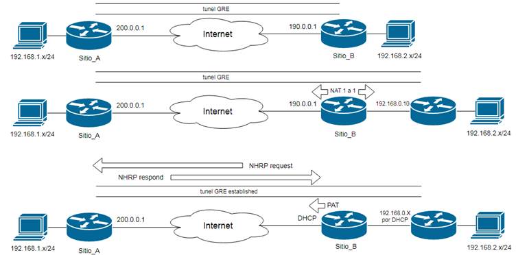
Escenario de tunel GRE con una IP dinámica en un extremo
Fecha: 4 y 5 de Octubre del 2011 Reeditado: 20 y 21 de abril del 2020
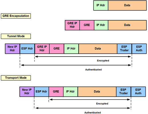
Escenario
Esta es una implementación del 2011 con
equipos reales (de producción) y nunca documenté.
Aprovechando la cuarentena y buscando
temas para estudiar retomé el análisis de este escenario, donde levantamos
un tunel
GRE entre dos routers Cisco 1811, pero que en uno de los extremos tenemos un
ISP con DHCP y que entrega
IP dinámicas, y en el otro extremo una
IP fija, como en todos los escenarios clásicos de CCNA. Las IP están cambiadas
por las usadas siempre en CCNA.
También se contempla proteger el tunel
GRE con un IPSec para darle seguridad en internet.
1.- Implementación en Sitio_A:
1.1.- Correspondiente al tunel GRE:
En la configuración del túnel
podemos ver varios detalles:
No tiene un destino
configurado, porque al utilizar NHRP los túneles son construidos dinámicamente
desde los extremos
hacia
el terminador de túneles.
También vemos que el modo de
túnel ha sido designado como GRE
multipoint ya que este podría ser parte de un escenario
DMVPN (Dynamic Multipoint VPN),
esto es, varios sitios remotos termiando túneles en un único punto y
compartiendo una
misma
subred, tal como eran los multipuntos Frame Relay.
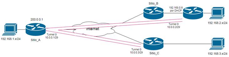
El comando ip nhrp network-id 1 identifica de manera única la red DMVPN, los
túneles sólo se establecerán con un mismo ID
de
túnel, esto permite al terminador formar grupos de túneles multipunto.
El comando ip nhrp map multicast dynamic habilita el reenvío de tráfico
multicast a través del túnel a los sitios remotos, lo
cual
es requerido por protocolos de enrutamiento como OSPF o EIGRP.
El comando ip mtu 1400 es para no exceder el tamaño debido a las cabeceras
GRE, NHRP e IPSec, debe ser IGUALES en ambos
extremos y llevaría a
fragmentar el paquete (ver laboratorio de fragmentación),
lo que no es saludable si utilizamos IPSec.
Este valor de MTU debe ser igual en ambos extremos
para establecer adyacencias OSPF (recordemos que deben concidir los
valores de hello, dead time y MTU).
En
el comando tunnel key
1 el router necesita una clave
de túnel para elegir el túnel correcto antes de que pueda desencapsular el
paquete y mirar la dirección IP. También en versiones viejas de
IOS, el tunnel key era una parte
obligatoria de la configuración del
túnel DMVPN, incluso si se usaba una sola interfaz de túnel.
Sin la clave configurada, NHRP simplemente no levanta.
Fuente: cisco.com
interface Tunnel0
description Tunel GRE a Sitio_B via VPN
ip address 10.0.0.1 255.255.255.252
ip mtu 1400
ip nhrp authentication ClaveSecret4
ip nhrp map multicast dynamic
ip nhrp network-id 1
ip nhrp holdtime 600
tunnel source FastEthernet1
tunnel mode gre multipoint
tunnel key 1
tunnel bandwidth transmit 512000
tunnel bandwidth receive 512000
Estos últimos dos comandos se
utilizan para especificar el valor de ancho de banda que se utilizará para
recibir o enviar paquetes
solo
a través del túnel. El valor predeterminado es 8000 Kbps.
Como diferencia, el comando bandwidth (BW) de una interface túnel no
se usa para regular el ancho de banda, sino que es utilizada
por
protocolos como EIGRP y OSPF para calcular métricas.
1.2.-
Correspondiente a OSPF:
router ospf 1
network 192.168.1.0 0.0.0.255 area 0 (red local)
network 10.0.0.0 0.0.0.3 area 0 (subred
del túnel)
1.3.- Correspondiente
IPSec:
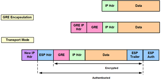
A diferencia de un escenario
IPSec tradicional, aquí utilizamos IPSec virtual tunnel interfaces (VTIs), que
proporciona
un
tipo de interfaz “enrutable” para terminar túneles IPsec (en logar de crypto-maps), y una forma fácil de
definir la
protección
entre sitios. Como detalle de utilidad a nuestro escenario OSPF, IPSec VTI
admite multicast.
1.3.1.- Definimos una preshared key que
permita cualquier origen esta clave es similar en ambos sitios:
crypto isakmp key
Pr3sh4reDKeY address 0.0.0.0 no-xauth (esto evita
que el router solicite el ingreso de user/pass)
1.3.2.- Definimos
cómo vamos a proteger nuestros datos:
crypto ipsec
transform-set TUNEL_GRE esp-aes 256 esp-sha-hmac
mode
transport (mantiene la cabecera IP del encapsulado GRE
para que se le pueda realizar NAT/PAT, ver abajo)
1.3.3.-
Creamos un perfil aplicable a una o varias interfaces:
crypto ipsec profile
Sitio_B (perfil de protección para el túnel)
set transform-set
TUNEL_GRE
set pfs group5 (grupo 5 de DH para intercambio de claves)
1.3.4.- Lo
aplicamos a la interface túnel:
interface Tunnel0
tunnel protection ipsec profile Sitio_B
2.- Implementación Sitio_B:
2.1- Correspondiente al tunel GRE:
interface Tunnel0
description Tunel GRE a Sitio_A via VPN
ip address 10.0.0.2 255.255.255.252
no ip redirects
ip mtu 1400 (igual al Sitio_A)
ip
nhrp authentication ClaveSecret4 (igual al Sitio_A)
ip
nhrp map 10.0.0.1 200.0.0.1
(IP física a alcanzar para negociar como cliente)
ip
nhrp map multicast 200.0.0.1 (para
transmitir OSPF)
ip
nhrp network-id 1 (igual al Sitio_A)
ip
nhrp holdtime 600 (igual al
Sitio_A)
ip nhrp nhs 10.0.0.1 (próximo salto (Next Hop Server))
tunnel source FastEthernet1
tunnel mode gre multipoint
tunnel key 1
tunnel bandwidth transmit 512000
tunnel bandwidth receive 512000
2.2.- Correspondiente a OSPF:
router ospf 1
network 192.168.2.0 0.0.0.255 area 0 (red local)
network 10.0.0.0 0.0.0.3 area 0 (subred
del túnel)
2.3.- Correspondiente IPSec:
crypto isakmp key
Pr3sh4reDKeY address 200.0.0.1 no-xauth (ahora si
apuntamos al terminador de túneles)
crypto isakmp nat
keepalive 10 (para mantener actualizada la tabla
PAT y que no caduque la traslación)
crypto ipsec transform-set
TUNEL_GRE esp-aes 256 esp-sha-hmac (igual al
Sitio_A)
mode transport (igual al Sitio_A)
crypto ipsec profile
Sitio_B (perfil de protección para el túnel, igual
al Sitio_A)
set transform-set TUNEL_GRE
set pfs group5
interface
Tunnel0
tunnel protection
ipsec profile Sitio_B (igual al Sitio_A)
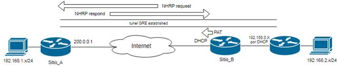
3.- Verificación:
3.1.- En el Sitio_A:
3.1.1.- Correspondiente al tunel GRE:
Sitio_A#sh
ip nhrp (creación del tunel GRE vía NHRP)
10.0.0.2/32 via 10.0.0.2, Tunnel0
created 01:05:09, expire 00:08:17
Type: dynamic, Flags: unique registered
NBMA address: 190.0.0.1 (IP ya
modificada (PAT) por el router del ISP)
(Claimed NBMA address: 192.168.0.10) (IP sin modificar (PAT) por el router del ISP)
Sitio_A#
Sitio_A#sh
dmvpn (creación del tunel GRE vía NHRP)
Legend: Attrb --> S - Static, D - Dynamic, I - Incompletea
N - NATed, L -
Local, X - No Socket
# Ent -->
Number of NHRP entries with same NBMA peer
Tunnel0, Type:Hub,
NHRP Peers:1,
#
Ent Peer NBMA
Addr Peer Tunnel Add State UpDn Tm Attrb
----- --------------- --------------- ----- --------
-----------------------------
1
190.0.0.1 10.0.0.2 UP never DN (ver atributos en negrita)
Sitio_A#
3.1.2.-
Correspondiente a IPSec:
Sitio_A#sh crypto isakmp sa (verifica fase I IPSec)
IPv4 Crypto ISAKMP SA
dst src state conn-id slot status
200.0.0.1 190.0.0.1
QM_IDLE 2008 0
ACTIVE (generado para recibir)
190.0.0.1 200.0.0.1
QM_IDLE 2009 0
ACTIVE (generado para transmitir)
Sitio_A#
3.1.3.-
Correspondiente a OSPF:
Sitio_A#sh ip ospf nei
Neighbor ID Pri
State Dead Time Address
Interface
192.168.1.0 0
FULL/ - 00:00:33 10.0.0.2 Tunnel0
Sitio_A#
3.1.4.- Tabla de enrutamiento:
Sitio_A#sh ip
route
Codes: C - connected, S - static, R - RIP, M - mobile,
B - BGP
D -
EIGRP, EX - EIGRP external, O - OSPF, IA - OSPF inter area
N1 - OSPF
NSSA external type 1, N2 - OSPF NSSA external type 2
E1
- OSPF external type 1, E2 - OSPF external type 2, E - EGP
i - IS-IS, L1 - IS-IS level-1, L2 - IS-IS level-2, ia - IS-IS inter area
* -
candidate default, U - per-user static route, o - ODR
P - periodic downloaded static route
Gateway of last resort is 200.0.0.2 to network 0.0.0.0
10.0.0.0/8 is
subnetted, 1 subnets, 1 masks
C
10.0.0.0/30 is directly connected, Tunnel0
C
192.168.1.0/24 is directly connected, FastEthernet0
O
192.168.2.0/24 [110/1001] via 10.0.0.2, 00:02:06, Tunnel0
200.0.0.0/24 is variably subnetted, 2 subnets, 2 masks
C
200.0.0.0/24 is directly connected, FastEthernet1
S* 0.0.0.0/0 [1/0] via 200.0.0.2
Sitio_A#
3.2.- En el Sitio_B:
3.2.1.- Correspondiente al tunel GRE:
Sitio_B#sh ip nhrp
10.0.0.1/32 via 10.0.0.1, Tunnel0 created 01:14:14, never
expire
Type: static,
Flags: nat used
NBMA address:
200.0.0.1
Sitio_B#
3.2.2.- Correspondiente a
IPSec:
Sitio_B#sh crypto isakmp sa
IPv4 Crypto ISAKMP SA
dst src state conn-id slot status
192.168.0.10 200.0.0.1 QM_IDLE 2094 0
ACTIVE (generado para recibir)
200.0.0.1 192.168.0.10 QM_IDLE 2093 0
ACTIVE (generado para transmitir)
Sitio_B#
Sitio_B#sh
crypto map
Crypto Map
"Tunnel0-head-0" 65536 ipsec-isakmp (mapa
de cifrado dinámico, recepción desde Sitio_A)
Profile name: Sitio_A
Security
association lifetime: 4608000 kilobytes/3600 seconds
Security
association idletime: 60 seconds
PFS
(Y/N): Y
DH group: group5
Transform sets={
TUNEL_GRE,
}
Crypto Map
"Tunnel0-head-0" 65537 ipsec-isakmp (mapa
de cifrado dinámico, transmisión al Sitio_A)
Map is a PROFILE INSTANCE.
Peer =
200.0.0.1
Extended
IP access list
access-list
permit gre host 192.168.0.10 host 200.0.0.1 (ACL generada automáticamente)
Current
peer: 200.0.0.1
Security
association lifetime: 4608000 kilobytes/3600 seconds
Security
association idletime: 60 seconds
PFS
(Y/N): Y
DH
group: group5
Transform sets={
TUNEL_GRE,
}
Interfaces using crypto map Tunnel0-head-0:
Tunnel0
Sitio_B#
3.2.3.-
Correspondiente a OSPF:
Sitio_B#sh ip ospf neighbor
Neighbor ID Pri
State Dead Time Address
Interface
200.0.0.1 0 FULL/
- 00:00:32 10.0.0.1 Tunnel0 (Sitio_A)
Sitio_B#
3.2.4.- Tabla de enrutamiento:
Sitio_B#sh ip
route
Codes: C - connected, S - static, R - RIP, M - mobile,
B - BGP
D -
EIGRP, EX - EIGRP external, O - OSPF, IA - OSPF inter area
N1 - OSPF
NSSA external type 1, N2 - OSPF NSSA external type 2
E1
- OSPF external type 1, E2 - OSPF external type 2, E - EGP
i - IS-IS, L1 - IS-IS level-1, L2 - IS-IS level-2, ia - IS-IS inter area
* -
candidate default, U - per-user static route, o - ODR
P - periodic downloaded static route
Gateway of last resort is 192.168.0.1 to network
0.0.0.0
10.0.0.0/8
is subnetted, 1 subnets, 1 masks
C
10.0.0.0/30 is directly connected, Tunnel0
C
192.168.0.0/24 is directly connected, FastEthernet1
O
192.168.1.0/24 [110/1001] via 10.0.0.1, 00:00:01, Tunnel0
C 192.168.2.0/24 is directly connected,
FastEthernet0
S* 0.0.0.0/0
[1/0] via 192.168.0.1
Sitio_B#
4.- Configuración de los equipos:
Sitio_A#sh runn (sólo lo mas
relevante)
Building configuration...
Current configuration : 995
bytes
!
version 12.4
!
hostname Sitio_A
!
crypto isakmp key
Pr3sh4reDKeY address 0.0.0.0 no-xauth
crypto isakmp nat
keepalive 10
!
crypto ipsec
transform-set TUNEL_GRE esp-aes 256 esp-sha-hmac
mode transport
!
crypto ipsec profile
Sitio_A
set transform-set TUNEL_GRE
set pfs group5
!
interface Tunnel0
description Tunel GRE a Sitio_B via VPN
ip address 10.0.0.1 255.255.255.252
ip mtu 1400
ip nhrp authentication ClaveSecret4
ip nhrp map multicast dynamic
ip nhrp network-id 1
ip nhrp holdtime 600
tunnel protection ipsec profile Sitio_A
tunnel source FastEthernet1
tunnel mode gre multipoint
tunnel key 1
tunnel bandwidth transmit 512000
tunnel bandwidth receive 512000
!
interface FastEthernet0
description INSIDE
ip address 192.168.1.1 255.255.255.0
ip nat inside
!
interface FastEthernet1
description OUTSIDE
ip address 200.0.0.1 255.255.255.0
ip nat outside
!
!
router ospf 1
log-adjacency-changes
network 10.0.0.0 0.0.0.3 area 0
network 192.168.1.0 0.0.0.255 area 0
!
ip route 0.0.0.0 0.0.0.0 200.0.0.2
!
!
end
Sitio_A#
Sitio_B# sh runn (sólo lo mas
relevante)
Building configuration...
Current configuration : 995
bytes
!
version 12.2
!
hostname Sitio_B
!
crypto isakmp key
Pr3sh4reDKeY address 200.0.0.1 no-xauth
crypto isakmp nat
keepalive 10
!
crypto ipsec
transform-set TUNEL_GRE esp-aes 256 esp-sha-hmac
mode transport
!
crypto ipsec profile
Sitio_B
set transform-set TUNEL_GRE
set pfs group5
!
interface Tunnel0
description Tunel GRE a Sitio_A via VPN
ip address 10.0.0.2 255.255.255.252
no ip redirects
ip mtu 1400
ip nhrp authentication ClaveSecret4
ip nhrp map 10.0.0.1 200.0.0.1
ip nhrp map multicast 200.0.0.1
ip nhrp network-id 1
ip nhrp holdtime 600
ip nhrp nhs 10.0.0.1
tunnel protection ipsec profile Sitio_B
tunnel source FastEthernet1
tunnel mode gre multipoint
tunnel key 1
tunnel bandwidth transmit 512000
tunnel bandwidth receive 512000
!
!
interface FastEthernet0
description INSIDE
ip address 192.168.2.1 255.255.255.0
ip nat inside
!
interface FastEthernet1
description OUTSIDE
ip address dhcp
ip nat outside
!
access-list 100 permit 192.168.2.0 0.0.0.255
!
ip nat inside source list 100 interface FastEthernet1
overload
!
router ospf 1
log-adjacency-changes
network 192.168.2.0 0.0.0.255 area 0
network 10.0.0.0 0.0.0.3 area 0
!
! (no
hay ruta por defecto porque se aprende por DHCP)
!
end
Sitio_B#
(2020) I can see the light at the end of the
tunnel...
Rosario, Argentina